- Draw an S-Curve
- Choose the Best Curve
- Get Control Points
- Get Arrow Angles
- Draw Bézier curve with React and SVG
- Demo
- Misc
- Updates
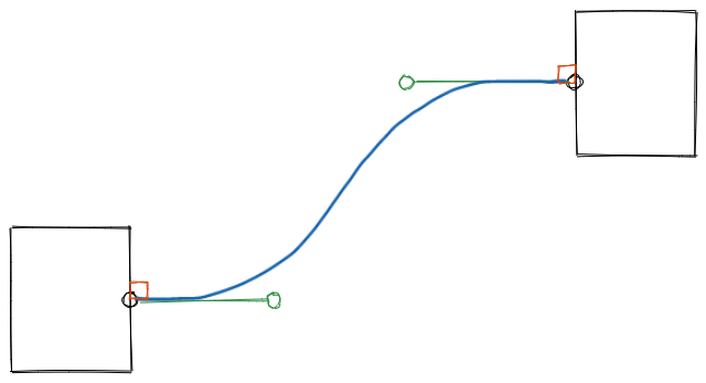
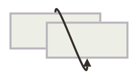
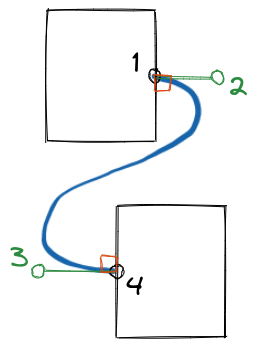
An S-curved arrow is a smooth curve that connects two boxes (or rectangles) like this:

Draw an S-Curve
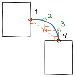
To draw the curve, one thing that came to my mind was “Bézier curve”. Its idea is to use control points to add curvature to a line. A control point bends the line once, so to bend it twice, we need two control points.

Like the above picture. Point 1 and 4 represent the start and the end of the curve, while point 2 and 3 are control points.
The next question is where the control points should be? Or how should they be generated?
Since the start and the end of the curve attach to the boxes, how about setting the start direction and the end direction to be perpendicular to the sides of the boxes?
Then, by extending the green bars, we can get to a point where two control points are on the same vertical line.
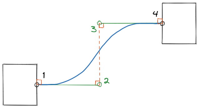
Now we get formulas. If the start point (1) is , the end point (4) is , then the control point (2) for the start point (1) is , the control point (3) for the end point (4) is .
Choose the Best Curve
We haven’t talked about where do the start point (1), , and the end point (4), come from, but from previous drawings you might have been wondering if they’re at the middle of the sides of the boxes.
Yeah, they are. To make arrows look clean when there’re many of them, we only allow them to start or end at the middle of the sides of the boxes. This also means we’ve narrow down the possibilities to 16 combinations to choose from.

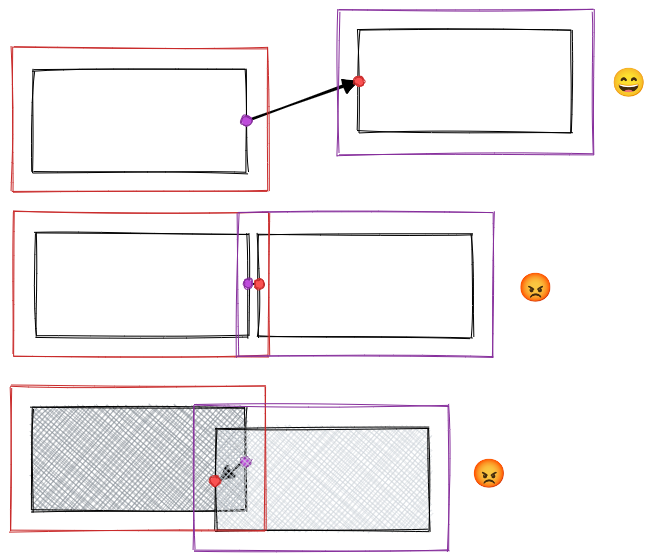
How to choose? Let’s consider this case:
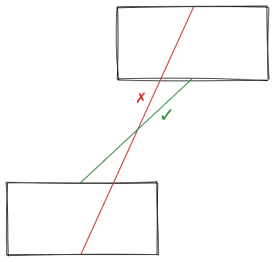
It seems that the one with the shortest distance is the best choice.
There’re some problems though.
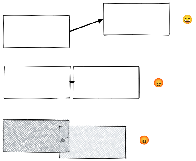
- If the boxes are close, the arrow would be barely visible.
- If the boxes overlap, the arrow may be hidden behind the boxes.
The solution is to add some rules to abandon combinations that are undesired.
This is an open question which can lead to many creative ideas about what is undesired and how to detect them, but for now, I designed and implemented a simple one that prevents the cases shown above.
I add keep-out zones to the boxes, and test if the end point is in the keep-out zone of the start box, or if the start point is in the keep-out zone of the end box, if a point does, combinations having that point would be abandoned.
There are still some corner cases though, but in Jade‘s use cases, blocks connected with arrows usually don’t overlap or get too close, so I’m going to leave them for you to figure out and make improvements if those are your serious use cases!
Get Control Points
I’ve mentioned a way to get control points for two boxes, but that is not the only case we would encounter in the real world.
The rule of thumb is that the control points must pull the curve out of a box, not into a box.

And the control points must be far away enough from their target points.

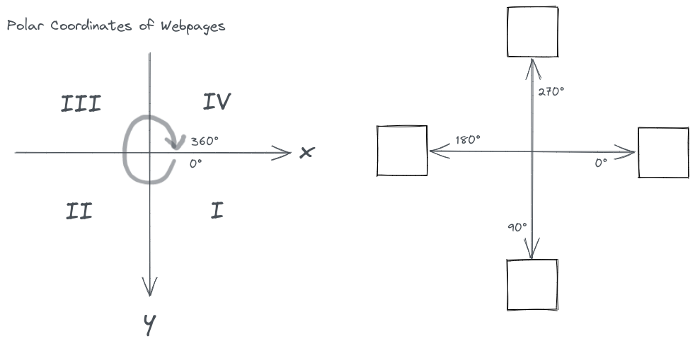
Get Arrow Angles
We also need to know the entering angles of the start point and the end point of the curve to draw arrow heads.
Draw Bézier curve with React and SVG
Now that we’ve get all parameters of an arrow, we can draw it with SVG using <path> and the Bézier curve command.
Here’s an example React component.
import * as React from 'react'
import { getArrow } from 'curved-arrows'

export function Arrow() {
  const p1 = { x: 100, y: 100 }
  const p2 = { x: 300, y: 200 }
  const arrowHeadSize = 9
  const color = 'black'
  const [sx, sy, c1x, c1y, c2x, c2y, ex, ey, ae] = getArrow(p1.x, p1.y, p2.x, p2.y, {
    padEnd: arrowHeadSize,
  })

  return (
    <svg
      width="100%"
      height="100%"
      xmlns="http://www.w3.org/2000/svg">
      <path
        d={`M ${sx} ${sy} C ${c1x} ${c1y}, ${c2x} ${c2y}, ${ex} ${ey}`}
        stroke={color}
        strokeWidth={arrowHeadSize / 2}
        fill="none"
      />
      <polygon
        points={`0,${-arrowHeadSize} ${arrowHeadSize *
          2},0, 0,${arrowHeadSize}`}
        transform={`translate(${ex}, ${ey}) rotate(${ae})`}
        fill={color}
      />
    </svg>
  )
}
Demo
Visualizing how it works ↓ You can also play here.
Misc
- I’ve made it an NPM package
curved-arrows, which you can install withnpm i curved-arrowsoryarn add curved-arrows. - The source code is on Github @dragonman225/curved-arrows.
- Author: Alexander Wang (@hialexwang)